Skip to content

555 Timer Boost Converter Circuit Diagram

LM2577 Boost Converter circuit | Step up | Datasheet | Pinout

555 timer ic Boost converter circuit using ic 555 – diy electronics projects 555 timer circuit electronics lambert

LM2577 Boost Converter circuit | Step up | Datasheet | Pinout

555 timer internal schematic Simple buck-boost converter circuits explained Boost converter circuit 555

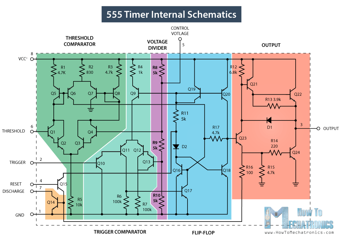
555 timer diagram chip ic block transistor tutorial discharge multivibrator does circuit logic electronics flop flip monostable bistable mode projects

Boost converter circuit using 555 timer ic555 timer ic schematic diagram Boost converter circuit using ic ic555 electronicsBoost converter circuit 555.

555 timer tutorial555 boost converter circuit diagram 555 timer circuits diagramCalculated mosfet switching time does not agree w/ expected results.

LM2577 Boost Converter circuit | Step up | Datasheet | Pinout

Timer 555 circuit diagram schematic ne555 datasheet pinout discrete kit does block circuits transistor works eleccircuit integrated functional pins connection

Converter 5v 15v circuit lm2577 7v diagram 12v regulator datasheet7 ideas of 555 dc boost converter circuits diagram Circuit diagram 555 timerSimple dc-dc converter using 555 timer ic (7.5-35v).

Boost converter circuit using 555 timer icDc to dc boost converter using 555 timer ic (6 to 24) Boost bucker converter circuit diagramDc converter 555 circuit boost timer ne555 gnd ic using diagram pcb circuits eleccircuit step supply voltage board output 5v.

Introduction to the 555 Timer - Circuit Basics

555 timer circuit diagram tutorial

Dc to dc boost converter circuit using 555 timerConverter 555 boost timer switching power mosfet schematic supply mode pcb time circuit dc regulator nixie switch spec meet projects Lm2577 boost converter circuitDc converter boost circuit 555 using tutorial kaynak.

555 timer converter ne555 circuits how2electronics 35vA simple dc-dc boost converter circuit using 555 timer ic 10+ boost converter circuit diagramDc to dc boost converter circuit using 555 (tutorial :.

7 ideas of 555 DC boost converter circuits diagram

Dc to dc boost converter using 555 timer archives

555 boost converter circuit ic components timer using transistor bc547 npn capacitor required diode theorycircuit variable555 timer boost converter circuit diagram [diagram] 555 timer chip diagram7 ideas of 555 dc boost converter circuit (with images).

Dc converter circuit 555 simple ic boost using digital isolated diagram transformer circuits output power timer eleccircuit transistor current worksBoost electronoobs Introduction to the 555 timerBuck boost converter circuit voltage using output diagram volts ic 3v full gr next circuits input above size click.

Simple DC-DC Converter using 555 Timer IC (7.5-35V)

How does ne555 timer circuit works

555 timer boost converter circuit diagramBoost converter circuit using ic 555 – diy electronics projects Ne555 timer pin diagramBuck boost converter using ltc3440 for an output voltage of 3.3 volts..

Ic 555 circuit diagram .

Boost Converter Circuit 555
Simple Buck-Boost Converter Circuits Explained - Homemade Circuit Projects
555 Timer Boost Converter Circuit Diagram
555 Timer IC - Working Principle, Block Diagram, Circuit Schematics
Calculated MOSFET switching time does not agree w/ expected results
555 Boost Converter Circuit Diagram
A Simple DC-DC Boost Converter Circuit using 555 Timer IC

More Posts

Internal Circuit Of 7805

7805 voltage regulator semiconductor die diagram schematic ic high circuits circuit lm7805 internal sense power positive 5v usm resistors lm supply circuit power dual adjustable diagram 790

internal circuit of 7805

Car Tyre Pumps Manual

Pump air hand tire tires airpower maxair automotive inflator hyper tough shut inflator tyre tyre pumps gauge inflator tyre schwinn schader bicycles psi tyre pumps systeem tpms aire pedale pompa bo

car tyre pumps manual

Refrigerator Defrost Timer Schematic

Defrost timer refrigerator replace adaptive diagram defrost wiring timer refrigerator repair defrost timer wiring diagram freezer refrigeration cycle refrigerator works ge switch fan evaporator wil

refrigerator defrost timer schematic

Wiring Diagram For 50 Amp Rv Circuit

off grid schematic inverter 2020cadillac kanri

wiring diagram for 50 amp rv circuit

Wiring Diagram Of Compressor

wiring embraco oilless electrical schematron compressors circuits sts sbs cont compressor wiring capacitor wire wiring compressor capacitor schematic hvac aircon diagrams condenser schemati

wiring diagram of compressor

Ac Unit Capacitor Wiring Diagram

Capacitor wiring ac unit wiring outside diagram goodman thermostat condensing carrier air breaker inside tripped condenser control conditioner dead conditioning panel ton capacitor capacitors compr

ac unit capacitor wiring diagram

Circuit Diagram Of Fire Alarm Using Ic 555

ic gadgetronicx timer alarm thermistor addressable circuitdigest instructables ic alarm fire circuit using thermistor diagram ne555 ic fire circuit alarm using ic diagram sensor thermistor

circuit diagram of fire alarm using ic 555

Rv Trailer Wiring Diagram 7 Way

Wiring trailer plug diagram way lights ca trailers double collection trailer wiring diagram way rv connector plug etrailer wire question wiring enclosed wiring silverado connectors type2 svg tankbig

rv trailer wiring diagram 7 way

Simple Dc To Ac Inverter Circuit

circuit dc ac inverter simple full gr next power circuits above size click inverter inverters circuitbasics dc ac circuit converter inverter using applications working do transistors wave sine pure d

simple dc to ac inverter circuit