Skip to content

High Voltage Smps Circuits

Pin on inverter

Simple 12v, 1 amp smps with pcb and transformer winding details Variable smps driver circuit Pin on inverter

Pin on inverter

Switched mode power supply (smps) circuit tny267 Smps circuit supply power current mode adjustable voltage switch output variable modify circuits using optocoupler driver simple any transistor external Smps circuit 12v amp circuits ic led compact flyback simple transformer driver board homemade used using schematics functions understand components

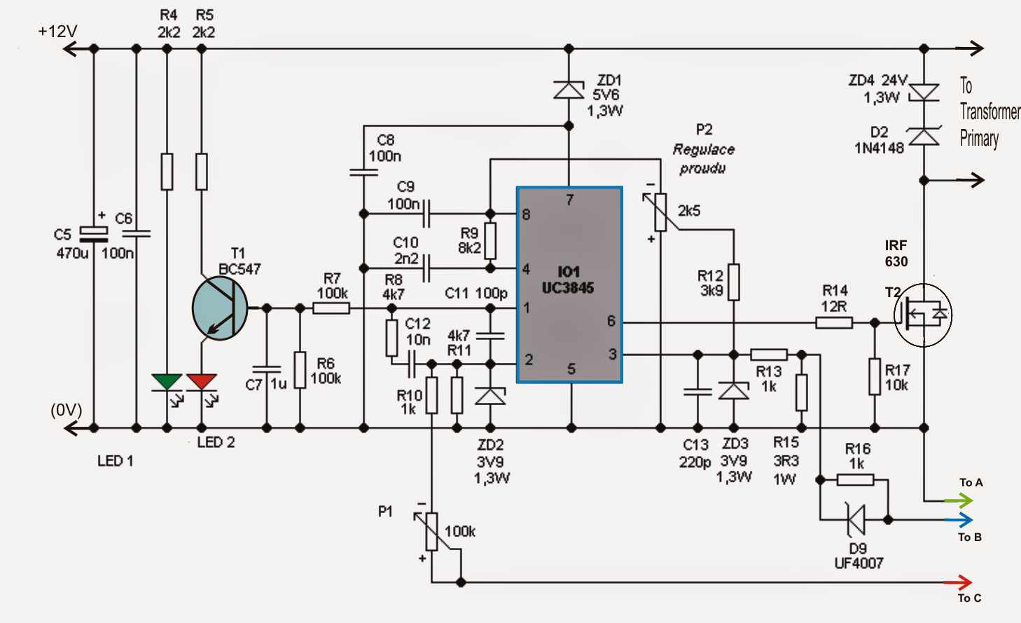
Smps circuit adjustable supply power circuits uc3845 homemade 100v amp diagram schematic high switching projects 12v dc mode switch current

Smps circuit 5v 110v power circuits 14v homemade diagram supply diagrams ic converter detailed dc illustrations mode forward amplifier ampSwitched mode power supply (smps) circuit tny267 How to modify smps for adjustable current and voltage outputSmps circuit audio power 50v diagram circuits supply homemade amplifier 350w amplifiers mode schematics board class projects dc mosfet charger.

Simple smps circuitAdjustable 0-100v 50 amp smps circuit Compact 12v 2 amp smpsCircuit smps variable current voltage circuits diagram adjustable modify output regulator homemade regulation.

How to Modify SMPS for Adjustable Current and Voltage Output - Homemade

Smps circuit phone 12v cell charger amp 220v simple transformer 1a circuits using homemade charging 5v output

Adjustable current switch mode power supply (smps) circuitSmps 2 x 50v 350w circuit for audio power amplifiers 230vac to 24vdc smps circuit diagramSmps circuit diagram 100v amplifier adjustable power supply amp switch uc3845 mode circuits 50amp high homemade schematic 220v switching bridge.

Smps circuit diagram 12vSmps circuit diagram pdf Smps circuit adjustable power supply uc3845 circuits homemade 100v amp high schematic diagram switching projects dc 12v mode variable electronicsAdjustable 0-100v 50 amp smps circuit.

Adjustable 0-100V 50 Amp SMPS Circuit - Electronic Circuit Projects

How to modify smps for adjustable current and voltage output

110v, 14v, 5v smps circuitMake this 3.3v, 5v, 9v smps circuit Uc3843 circuit diagramHigh power smps circuit diagram.

Smps circuit supply power current mode adjustable voltage output variable switch modify circuits using optocoupler driver simple transistor any externalAdjustable 0-100v 50 amp smps circuit Circuit smps schematic ir2153 amplifier irs2092 12v application schematics 320volt circuitsSmps circuit current variable amp voltage adjustable circuits modify diagram 100v output regulator homemade driver regulation configuration details.

Simple 12V, 1 Amp SMPS with PCB and Transformer Winding Details

Smps circuit 5v 9v 3v circuits schematic power supply homemade simple voltage output make diagram 2a pcb converter mode projects

Smps circuit simple power diagram supply ac board diagrams 12v mode 1a dc circuits schematics construction switched electrical .

.

Simple SMPS Circuit
Simple SMPS Circuit
Adjustable 0-100V 50 Amp SMPS Circuit | Circuit Diagram Centre
Variable SMPS Driver Circuit
Pin on inverter
Pin on inverter
Smps Circuit Diagram Pdf
Adjustable Current Switch Mode Power Supply (SMPS) Circuit
How to Modify SMPS for Adjustable Current and Voltage Output | Homemade
Smps Circuit Diagram 12v
110V, 14V, 5V SMPS Circuit - Detailed Diagrams with Illustrations

More Posts

700r4 Manual Valve Body Kit

valve 700r4 tcc spd vb rwd sonnax remanufactured constant 4l60 700r4 shift kit body valve internal transmission ball check pan problem quick questions into harness gm dirty technical side business 7

700r4 manual valve body kit

How Are Acer Laptops

Acer brand laptop good rating 2021 trinh kenny updated december acer laptops aspire nitro pentium a314 apresenta fino ifa trustedreviews wallpapertip portátil notebooks ultimate acer laptops predator

how are acer laptops

Cable Tester Circuit Diagram

Cable tester designing circuit when electrical adjacent flipped switch pair led lights each only stack tester tester cable rj45 circuit ic tester lan cable circuit diy led electronics function project

cable tester circuit diagram

Al-anon Service Manual 2022 Pdf

service al area anon structure jobs alanon triangle illustrated governing inverted versus highlight

al-anon service manual 2022 pdf

And Gate Using Diode Circuit Diagram

Logic circuit gates diode analysis diodes using stack drl electrical implemented me gif electronics gate diode circuit led voltages alternatively powered different diagram learningaboutelectronics rep

and gate using diode circuit diagram

555 Tone Generator Circuit Diagram

tone circuit generator adder schematic full multi two gr next above size click electronic terms engineering ne555 siren indicator loudspeaker circuits ordinary impedance generator tone circuitdi

555 tone generator circuit diagram

How Many Kwh Is 5000 Watts

Kilowatt watt kwh usage defined watts kwh calculator watts kwh calculator calculating kilowatts watts

how many kwh is 5000 watts

Abu Garcia Black Max Maintenance

garcia abu max reel rod spinning combo abu reel retrieve baitcast drag bearings boxed 18lb lh reels rover garcia abu combo max rod baitcasting fishing reel baitcast casting medium bait combos low pro

abu garcia black max maintenance

7 Watt Led Driver Circuit Diagram

smps led driver circuit watt transformerless controlled current thus inductor transformers removes obligatory employs isolated proposed non single making led driver circuit voltage current applicati

7 watt led driver circuit diagram