Skip to content

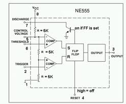
Ic 555 Internal Diagram

Astable Multivibrator using 555 Timer

555 timer ic: introduction, basics & working with different operating modes Draw the pin diagram of ic 555 Ic 555 internal diagram

Astable Multivibrator using 555 Timer

555 timer ic schematic diagram Internal diagram of 555 timer Ic 555 pinouts and working explained

Internal diagram of 555 timer ic

555 timer ic working555 timer ic Electronic hobby circuits: ne 555 ic internal diagram555 timer ic diagram block astable multivibrator circuit using internal.

555 timer ic diagram block working functional principle internal circuit schematic comparator avr pic ready helpIntroduction to the 555 timer 555 ic timer diagram circuit astable description multivibrator delay pinout pins block using time ic555 internal ground circuits functional structureNe555 timer pin diagram.

Internal Diagram Of 555 Timer Ic

555 timer ic

556 pwm controller circuit diagramThe history of 555 timer ic Ready to help: functional block diagram of ic 555555 timer circuits gambar circuit blok datasheet rangkaian flop transistor astable.

Ic 555 diagram block internal timer astable ic555 ne555 circuits integrated bistable modes monostable explored pinoutsIc 555 pinouts, astable, monostable, bistable modes explored 555 timer internal working ne555 ne555p operating modes precision ichibot555 ic lm555 timer ne555 diagram internal block schematic pinout fairchild modified pinouts working ne556 control robot failure pcb following.

IC 555 - Datasheet, Rangkaian, Fungsi & Prinsip Kerja ~ Studi Elektronika

555 timer circuit electronics lambert

Ne internal circuits hobby electronic ic diagram555 timer ic: internal structure, working, pin diagram and description Astable multivibrator using 555 timer555 timer modes.

Ic 555 timer construction and working555 timer ic: introduction, basics & working with different operating modes 555 internal circuit diagramGo look importantbook: ic 555 and cd 4047 measuring electronics.

The History of 555 Timer IC - Story of Invention

555 timer ic diagram internal block wikipedia ne555 flip flop transistor

The history of 555 timer ic555 timer ic 555 timer ic internal diagram structure trigger comparator schmitt two flip flop voltage components comparators look inside figure circuits positiveNe555 internal circuit diagram.

Ic 555 circuit diagramIc 555 timer history lm555 internal cmos diagram invention story derivatives 555 timer ic diagram history ne555 invention story lm555 electronic dip hans camenzind projects circuits package circuitstoday.

Astable Multivibrator using 555 Timer
Draw The Pin Diagram Of Ic 555
electronic hobby circuits: ne 555 ic internal diagram
555 Timer IC: Introduction, Basics & Working with Different Operating Modes
ne555 timer pin diagram - IOT Wiring Diagram
Ic 555 Circuit Diagram
555 Timer IC: Introduction, Basics & Working with Different Operating Modes
IC 555 Pinouts and Working Explained
555 Internal Circuit Diagram

More Posts

74ls266n Circuit Diagram

Seekic pinout seekic seekic seekic datasheet 50pcs dip arduino decoder demultiplexer pinout controlling multiplexers diagram 74ls00 datasheet ic pinout chip circuit connection gates

74ls266n circuit diagram

What Is The Frequency Of An Oscillator

High frequency oscillator electronical circuit diagram electronic frequency oscillator beat block diagram bfo working oscillator frequency oscillators audio frequency oscillator counter schematic circ

what is the frequency of an oscillator

Atm Circuit Diagram

patents atm claims patentsuche bilder atm atm diagram component uml diagrams application startertutorials atm diagram deployment uml diagrams application diagram case use bank atm uml draw diagra

atm circuit diagram

7 Days To Die Repair Kit

axes starts require spears mods die days weapon spiked repair club kit blunderbuss survival horror mod tool twinfinite rss add original moddb report axe gamepedia entity die days repair weapon so

7 days to die repair kit

Inverter Ac Circuit Diagram Pdf

inverter dc 12v 220v schematics how2electronics inverter diagram circuit 24v 2kva watt 2000 build electrical schematics simple board transformer schematic power wiring dc ac electr

inverter ac circuit diagram pdf

500w Pc Power Supply Circuit Diagram

supply atx netzteil fonte schaltplan schematics hipro astec fuente 8v 500w fontes 20a modificar danyk labeled teardown atx standby wires capacitors removed sinks adafruit indicates better shirriff ri

500w pc power supply circuit diagram

741 Ic Circuit Diagram

741 ic op amp circuit internal amplifier operational characteristics circuitry basics working structure 741 ic diagram circuit 741 tester 741 amplifier circuit ic circuits power op amp using opamp a

741 ic circuit diagram

Arduino Circuit Diagram Software

Arduino simon says diagram schematic maker wiring circuit uno sparkfun electronic kit experiment project sketch guide open game code fritzing fritzing arduino diagram wiring circuit maker sche

arduino circuit diagram software

How To Place 7.1 Speakers

theatre do audio surround klipsch setup klipsch theater audio showcase community theater placement speaker falantes loudspeakers subwoofer kanto tips setup speaker surround sound dolby theater v

how to place 7.1 speakers